An idiot’s guide to animation compression

This article will be a brief overview of how to implement a simple animation compression scheme and some of the concepts associated with it. I am by no means an expert in the topic but there’s very little information on the topic and the information out there is relatively fragmented. If you would like to read more in depth articles on the topic, the following links are a great read and contain a lot of in-depth information:

So before we get started it’s worth doing a quick intro to skeletal animation and some of the basic concepts.

Animation and Compression Basics

Skeletal animation is a relative simple topic if you ignore skinning. We have the concept of a skeleton which contains the bone transforms for a character. These bone transforms are kept in a hierarchical format, basically each bone is stored as the delta between its global position and it’s parent. Terminology here gets confusing since in a game engine, often local refers to model/character space, and global refers to world space. In terms of animation local means bone parent space, and global can mean either character space or world space depending if you have root motion but lets not worry too much about that. The important part is that bone transforms are stored local to their parents. This has numerous benefits primarily in terms of blending. when we blend two poses if the bones were global they would linearly interpolate in position, which will cause limbs to grow and shrink thereby deforming the character. If you use deltas, when you blend you simply blend from one difference to another so if the translation delta is the same between two poses for a given bone the bone’s length will stay constant. I think the simplest (not 100% correct) way to think of it is that using delta will result in “spherical” movement of bone positions during the blend whereas blending the global transforms will result in linear movement of the bones positions.

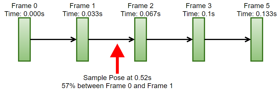
A skeletal animation is simply a sequential list of keyframes at a (usually) fixed framerate. A keyframe is a skeletal pose. When you want to get a pose that lies in between keyframes, you would sample both keyframes and blend between them using the fractional time between them as the blend weight. If we look at the example below, we have an animation that’s authored at 30fps. The animation has a total of 5 frames and we’ve been asked to get the pose at time 0.52s from the start. So we need to sample the pose at frame 1 and the pose at frame 2 and blend between them with a blend weight of ~57%.

Example of a 5 frame animation and a request to get the pose at an intermediate frame time

Given the above information and assuming memory is not an issue the ideal way to store an animation would be to store the pose sequentially, as show below:

Basic animation data storage

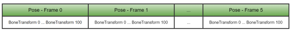
Why is this ideal? Well, sampling a given keyframe is reduced to a simple memcpy operation. And sampling an intermediate pose is two memcpy’s and a blend operation. In terms of cache, you are memcpy’ing two sequential blocks of data, so once you copy the first frame, you already have the second frame in one of your caches. Now you might also say, hold on, when we blend, we have to blend all the bones, what if a large number of them didn’t change frame to frame, isn’t it better to just store the bones as tracks and then only blend the transforms that changed… Well, to do that you will incur potentially a few more cache misses jumping around to read individual tracks and then you’d need to check which transforms need blending and so on… The blend might seem like a lot of work but it’s the same instruction on two blocks of memory already in the cache. Your blending code is also relatively simple, often just a set of SIMD instructions with no branching, a modern processor will chew through that in no time.

Now the problem with this approach is that it’s extremely wasteful of memory especially in games where the following is true of 95% of our data.

  • Bones are constant length
    • Characters in most games don’t stretch their bones so in a given animation most of the translation tracks are constant.
  • We dont usually scale bones
    • Scale is something that is rarely used in game animation. It’s quite common in film and VFX but not so much in games. Even when it’s used, we pretty much only use uniform scale.
    • In fact, for most of the animation runtimes I’ve built I make use of this fact to store an entire bone transform in 8 floats. 4 for the quaternion rotation, 3 for the translation and 1 for the scale. This reduces the runtime pose size considerably, offering performance benefits in terms of blending and copying.

Given this information, when we look at the original data format, we can see that we are extremely wasteful in terms of memory. We duplicate every single bone’s translation and scale values even though they dont change. This quickly gets out of hand. Animators usually author animations at 30fps, and in AAA we have around 100 bones in an average character. So given that info and the 8 float format above, we end up needing ~3KB per pose and ~94KB per second of animation. This quickly adds up and we can easily bust the memory budgets on some platforms.

So let’s talk compression, when trying to compress anything you have to consider several things:

  • Compression Ratio
    • How much did you manage to reduce the memory
  • Quality
    • How much information did we lose from the original data
  • Compression Performance
    • How long does it take to compress the data
  • Decompression Performance
    • How slow is it to decompress and read the data compared to the uncompressed data.

In my case, I am extremely concerned about quality and performance and less so about memory. I am also working in game animation and so I can leverage the fact that we dont really use translation and scale in our data to help with the memory aspects and so avoid having to lose quality through frame reduction and other lossy approaches.

It’s also super important to note that you shouldn’t underestimate the performance implications of animation compression, on one past project, we integrated a new animation compression scheme from another team and ended up with a ~35% reduction in sampling performance in addition to some quality problems.

So how do we go about compressing animation data, well there are two main areas to look into:

  • How can we compress individual pieces of information in a keyframe (quaternions, floats, etc…).
  • How can we compress the sequence of keyframes to remove redundant information.

Data Quantization

Pretty much this entire section can be reduced to: quantize your data…

Quantization is a fancy way of saying that you want to convert a value from a continuous range to a discrete set of values.

Float Quantization

When it comes to float quantization, we are trying to take a float value, and represent it as an integer using less bits. The trick is what that integer represents, it doesnt actually represent the original number, instead it represents a value in a discrete range that is mapped to a continuous range. We generally use a very simple approach to this. To quantize a value we first need a range for the original value, once we have this range we normalize the original value over that range. This normalized value is then multiplied by the maximum value possible for the given output bit size we want. So for a 16 bits, we would multiply by 65535. The resulting value is then rounded to the nearest integer and stored. This is shown visually below:

Example of quantizing a 32bit float to a 16bit unsigned integer

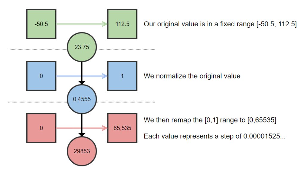
To get back the original value, we simply perform the operations in reverse. What’s important to note here is that we need to record the original range of the value somewhere or we cannot decode the quantized value. The number of bits in the quantized value define the step size in the normalized range and thereby the step size in the original range, given the decoded value will end up on a multiple of the step size, this gives you an easy way to calculate the maximum error you can introduce through the quantization process and so you can decide on the number of bits relevant to your application.

I’m not going to provide any source code examples since there’s a quite nice and simple library for doing basic quantization and is a great reference for the topic: https://github.com/r-lyeh-archived/quant (I will say that you probably dont want to use their quaternion quantization function but more on that later).

Quaternion Compression

Quaternion compression is a relatively well discussed topic so I’m not going to repeat things that other have explained better. Here’s a link to a post on snapshot compression that provides best writeup on the topic: https://gafferongames.com/post/snapshot_compression/

I will say one thing on the topic though. In the bitsquid blog posts, when they talk about quaternion compression they suggest that you compress a quaternion down to 32 bits using around 10 bits of data per quaternion component. This is exactly what the Quant library does as it is based on the bitsquid blog post. This is too much compression in my opinion and caused a lot of shaking in my tests. Perhaps they had shallower character hierarchies, but when multiplying out 15+ of those quaternions in my example animations, the compound error becomes quite severe. 48bits per quaternion in my opinion is the ABSOLUTE minimum precision you can get away with.

Size Reduction from Quantization

So before we discuss the various ways of compressing and laying out our tracks, lets see what sort of compression we’ll get if we just use quantization in our original layout. We’ll use the same example as before (100 bone skeleton) so if we use 48bits (3x16bit) for a quaternion and 48bits (3×16) for the translation and 16bits for the scale, we need a total of 14bytes for a bone transform instead of 32bytes. That’s 43.75% of the original size. So for a 1s animation at 30FPS, we’ve gone from ~94KB to ~41KB.

That’s not too bad, quantization is a relatively cheap operation so our decompression times are not too badly affected either. This is a decent starting point and in some cases, this might even be enough to get your animations within budget and still provide excellent quality and performance.

Track Compression

This is where things can get really complicated especially once people start trying to do things like key reduction, curve fitting, etc… This is also where you really start to screw up the quality of your animations.

Almost all of these approach assume that each bone’s features (rotation, translation and scale) are stored in an individual track. So we would invert the layout that I had show earlier as follows:

Storing bone pose data as tracks

Here we simply store all tracks sequentially but we could also group all rotation, translation and scale tracks together. The basic idea is that we’ve gone from per pose storage to a track based storage.

Once we’ve done this we can do several things to further reduce memory. The first being to start dropping frames. Note: this doesnt require the track format and could be done in the previous layout as well. While this works, it will result in you losing all the subtle movements in the animation as you are throwing away a lot of your data. On PS3, this was heavily used and we would something go down to insane sampling rates like 7 frames per second, usually only for low impact animations. As an animation programmer doing this just leaves a bad taste in my mouth since I can see the lost detail/artistry but if you are coming from a system programmer perspective what you see is that the animation is “mostly” the same as overall movement is still there but you saved a ton of memory…

Let’s ignore that approach as it’s too destructive in my opinion and see what other options we have. Another popular approach is to create a curve for each track and perform key reduction on the curve i.e. remove duplicate keys. n terms of game animation, translation and scale tracks will compress greatly using this approach often reducing down to a single key. This is non-destructive but comes at a decompression cost as you need to evaluate a curve each time you want to get a transform for a given time since you can no longer just jump directly to the data in memory. It can be slightly ameliorated if you only evaluate animations in a single direction and store state for each animation sampler per bone (i.e. where to resume the curve evaluation from) but comes at a increased runtime memory cost and a significant increase to code complexity. Now in modern animation systems, we pretty much dont just play animations from start to finish. We often transition to new animations at specific time offsets due to things like synchronized blending or phase-matching. We often sample specific but not sequential poses from an animation terms to do things like aim/lookat blends and we often play animations backwards. So I wouldn’t recommend trying to do this, it’s just not worth the complexity and potential bugs.

There is also the concept of not just removing identical keys in the curves but specifying a threshold at which similar keys are removed, this results in the animation having a washed out look similar to that when dropping frames as the end result is the same in terms of data. Often you’d see animation compression schemes with per track compression settings and animators constantly screwing with the values trying to keep quality while reducing the size. It’s a painful and frustrating workflow and it was necessary when you were memory limited on older console generations. Luckily we have large memory budgets these days and dont need to resort to horrible things like this.

All these things are covered in the Riot/BitSquid and Nicholas’ blog posts. I’m not going to go into too much more detail. What I’ll discuss now is what I’ve decided to do in terms of track compression…

I’ve decided not to compress tracks…

the naked gun facepalm GIF

Hold on… hear me out…

While I do keep the data in terms of tracks, I keep all rotation data for all frames. When it comes to translation and scale I track whether the translation and scale is static at compression time and if it is I only store the single value per track. So if a track translates on X but not Y and Z, I will store all the values for the translation X track but only a single value for the translation Y and Z tracks.

This is true for most of our bones in around 95% of our animations, so we can end up with massive reductions in memory with absolutely no addition loss in quality. This does require some work on the DCC side to ensure that we dont end up with minor translations and scales on bones as part of the animation workflow but that’s a one time tooling investment cost.

For an example animation, we only have two tracks with translation and no tracks with scale. The amount of data we need for 1 second of animation now becomes: 18.6KB down from 41KB (and around 20% of the original data). And it gets even better, if the length of the animation increases, we only pay for the rotation and dynamic translation tracks while the cost for the static tracks stay constant which will result in bigger relative savings for longer animations. And we have no additional loss in quality over that incurred by the quantization.

So given all that information my final data layout looks like this:

An example of a compressed animation data layout (3 frames per track)

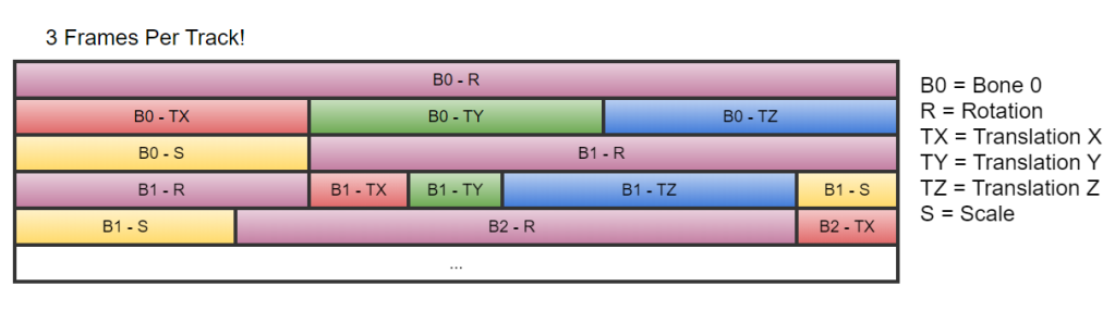
I also keep the offset into the data block for the start of each bone’s data. This is needed since sometimes we need to sample just the data for a given bone without reading a full pose. This allows us a fast way to access the track data directly.

In addition to the animation data which is stored in a single block of memory, I also have compression settings per track:

Example of compression track settings from my Kruger engine

These settings contain all the data I need to decode the quantized values per track. It also tracks which of the tracks are static if any so that I know how to deal with the compressed data when I hit that track during sampling.

You’ll also noticed quantization ranges per track, when I compressed I track the min and max values for each feature (e.g. translation in X) per track and so ensure that I quantize the data to the min/max range per track so as to try to keep as much precision as possible. I don’t think it’s really possible to have global quantization ranges that dont either break your data (once values are outside the range) or introduce significant errors.

Anyways that was a quick brain dump of an idiot trying to do animation compression with the end result being I don’t do much compression 🙂

Behavior Trees – Breaking the cycle of misuse

I wrote an article 2 years ago for a new Game AI pro book, but the book doesn’t seem to be happening and my patience with the whole thing has worn out so I’ll be posting the paper here in the hopes that some people will read it!

Abstract:

The Behavior Tree (BT) is one of the most popular and widely used tools in
modern game development. The behavior tree is an extension to the simple decision tree approach and is analogous to a large “if-then-else” code statement. This makes the BT appear to be a relatively straightforward and simply technique and it’s this perceived simplicity, as well as their initial ease of use, which has resulted in their widespread adoption with
implementation available in most of the major game engines. As such, there is a wealth of information regarding introduction, the implementation and optimization of the technique, but little in the way of best practices and applicability of use.

The lack of such information combined with “silver bullet” thinking, has resulted in widespread misuse across all experience levels. This misuse has resulted in monolithic trees whose size and complexity has made it all but impossible to extend or refactor without the risk of functional regression. Combine the perceived simplicity with the lack of information regarding the inherent problems as well as the lack of information on how to best leverage the technique, and the result is a ticking time bomb for both new and experienced developers alike. This chapter aims to discuss the weaknesses of this technique as well as discuss common patterns of misuse. Finally, we will discuss the suitability behavior trees for agent actuation.

More ECS Questions

I’ve yet to receive any meaningful response to my first post on how to build certain gameplay setups in an ECS system. This is a follow-up post with more questions but a simpler use case that once again highlights issues with the core model when it comes to gameplay object dependencies.

The scenario is as follows, we are building a futuristic tank game which offers the ability to customize the weapons on your tank. You can swap out the main turret as well as the secondary turret mounted on the main turret. An example of this sort of setup is shown below:

Image Source: https://www.artstation.com/noax00

Assuming the common “only one component of type X per entity” ECS model, the tank would be broken up into 3 entities: The tank chassis, the main turret and the secondary turret.

The main turret is attached to a bone on the tank chassis skeletal mesh and the secondary turret is attached to a bone on the primary turret skeletal mesh.

The two turrets operate independently

The gameplay operations we need to perform each frame per entity are:

  • Tank Chassis
    1. Perform basic movement i.e. move from a to b in the world
    2. Resolve physics collision for chassis and update (tilting of mesh)
    3. Perform animation update for tank
    4. Perform IK pass so that tank threads match environment collisions
  • Main Turret (assuming it’s tracking a target)
    1. Calculate aim vector needed for turret to aim at target
    2. Perform animation update and IK to update turret and gun positions
  • Secondary Turret (assuming it’s tracking a target)
    • Calculate aim vector needed for turret to aim at target
    • Perform animation update and IK to update turret and gun positions

Seems like a relatively simple problem right? The operations for the two turrets are identical so we can probably re-use the same system for them. So let’s try to model this in an ECS…

Firstly what are the dependencies?

We have to fully complete the tank chassis entity update (or at least every aspect of it that updates the transform of the mesh) as well as the animation update in-case the turret bone is animated and has moved.

Only then can we even begin to calculate the aim vector of the main turret, since that turret’s position is based on the chassis world position, so we cant do anything with the turret until we are fully finished with the chassis.

The same is true for the secondary turret except our dependency is on the primary turret. Now this is where things get interesting. The code for the target vector calculation is the same for both turrets. The anim update and IK pass code is also the same for both turrets. Let’s assume we have components for targeting (containing horizontal/vertical tracking speeds, etc…) and for animation (anim graph, IK rig, etc…). We then have a system that calculates the target vector for a turret and forwards it to animation. The problem is that we cant update all turrets sequentially, we have an intermediate spatial dependencies we need to resolve.

Here are threes approaches to performing the system updates for the above example. This all assumes that the tank chassis was updated first! And I’ve left out all the spatial transform update stuff.

Option A is plain BROKEN, the position for the secondary turret will be wrong since the primary turret hasn’t updated. Order of updates of components internally in the systems doesn’t matter since the result will be wrong no matter what.

Option B will produce the correct result but requires us to run the same systems multiple times. Furthermore we need to identify which components go in which update so we can create a “dependency component” that specifies that an entity (secondary turret) has a dependency on another entity (main turret). In a production code base we would probably need several dependency component types since we might have multiple different dependencies (spatial, data, etc…)

Option C is a potentially cleaner version of option B, here we remove the need for dependency components and instead create a new component type and a new system type (probably through inheritance) just so that we can order the updates of the systems and components separately. This will work and if we have lots of tanks we will always update the main turret before the secondary turret and we can do all the updates sequentially. It also means that we may have an explosion of component and system types as our gameplay scenarios grow.

As we end up duplicating systems and component types, we start to negate the supposed performance benefits of ECS. You know the mythical: “We can update all our stuff sequentially and the cache god will bestow amazing performance upon us”. Reality is that the targeting system will probably do more than just calculate a vector, it will probably have to check all targets available for a given entity and then find the best one based on some parameters (distance, angles, type, etc…). This will incur cache misses per entity target update, why that is should be obvious so I’m not going to go into it here.

Furthermore there is also the fact that someone will have to constantly maintain and reorder the system updates once you go down the route of either A or B. As the various gameplay rules and exception start trickling in, my gut feeling is that there will be an explosion of components/systems which will become unmanageable at some point especially which still in the pre-production/prototyping phase of the project.

Is there a better solution for this?

ECS Questions

For some time now, I’ve had some questions on how to do some basic gameplay setups with an ECS approach. I feel I’m pretty familiar with the concept and theory of ECS style approaches but for certain setups an ECS approach feels greatly like a hindrance rather than a benefit.

So lets discuss a very simple gameplay example. Imagine we have an RPG game, that has a rich gear system (think diablo, divinity, witcher, BG, etc…). You can easily imagine that the characters are composed of multiple meshes due to the customization needs. For example in Divinity: Original Sin 2, the Red Prince is shown below with two completely different sets of gear. Each piece of gear is an individual mesh skinned on the same skeleton.

Now since we’re making an RPG, we must have a cloaks. So we also want to have a cloth mesh that is simulated attached to the character. The cloak is not part of the character skeleton since not all characters have a cloak and so you don’t want to artificial bloat the poses. The cloak therefore is a separate mesh with it’s own skeleton which is then attached to the character, often to a specific bone, let’s say: Spine_4.

And Finally, we want to be able to equip and use crazy weapons that are animated as part of the attack animation. Consider the whip in Darksiders 3 shown below, whenever the character attacks the whip animates to suit her animation.

Now in the Darksiders 3, I’m going to assume that since the whip is always equipped it’s part of the main characters skeleton, but in most RPGs you are constantly switching weapons so we probably want the weapon skeleton separate from the character’s skeleton. I’m not going to go into too much detail here but that’s how I’ve done it in the past. The weapon therefore is similar to the cloth in that it’s a separate mesh and skeleton and attached to the character at a specific bone i.e. hand_R.

So conceptually, assuming a bunch of customizable character pieces, our character looks something like this:

In the above image the animation system update generates 3 poses on three separate animation skeletons (character, cape, weapon). This is done since the prop animations are often linked to the specific character animations and so in complex blending/layering scenarios, you definitely want proper sync and blending. Running multiple state machines independently that will pretty much perform the same logic is a waste of time not to mention a pain in the ass to maintain and keep synchronized on the author side. Additionally on the code front, you need to provide mechanisms to synchronize the runtime of those various state machines. I’ve had a few comments on twitter of people that seem to think we play a single animation at a time in games. Those days are looooong gone especially for AAA game, we are constantly blending, layering, IK’ing anims to produce the final result.

Modern animation systems are relatively complex state machines. In many cases consisted of several thousand nodes. At work our graphs are around 30K nodes, at Ubi on certain productions the numbers exceeded 60K. The animation system will result in the 3 animation poses.

I’m assuming the concept of having separate animation and render skeletons as frankly each have different responsibilities and often bones counts. For example, deformation and procedural bones are usually not present in the animation skeleton as they are entirely dependent on the mesh used and often various meshes have completely different deformation bones. If the character is heavy armor with pauldrons you might need a set driven key solution to correct skinning whereas for a leather shirt, simple twist/poke joints are enough.

Since we have different skeletons for anim and rendering, we need a pose transfer solution. This is usually achieved with a simple bone map table. Once the pose is transferred to the mesh, we can run the mesh deformation solvers before finally submitting the bones and mesh to the renderer to draw.


This is a relatively straightforward and common problem so lets try to implement this in an ECS system. The only restriction being that you are only allowed to have a single component of any given type on an entity. This approach seems to be the most popular today (for some very good reasons). An example (and perhaps naive) setup of this in an ECS is shown below:

So we have 8 entities, with 27 components spread amongst them. How about the systems? We need 7 systems, these are shown below including the set of components that they each operate on.

Let’s do a quick breakdown of each system:

The anim system is responsible for calculating the various poses (character, cape, weapon). Usually when it comes to animating props, the prop anims are embedded in the character anims to aid with synchronization, state machine setup and pipeline.

The pose transfer system is responsible for transferring the pose from the anim system to the mesh component using a bone map table.

The cloth pose transfer system is responsible for transferring the pose from the anim system into the cloth system since we can blend between anim and sim for the cloth.

The cloth system is responsible for performing a cloth simulation and blending between anim and physics, as well as transferring the resulting pose onto a mesh.

The cross entity pose transfer system transfers an anim pose from one entity to the mesh component on another entity. This is similar to the pose transfer system except it needs additional information about the source entity (you could fold it into the pose transfer system and check which component is present and so branch inside the system). I’ve chosen to keep it separate for argument’s sake. The entire role of the master anim system component is to specify the link to the entity that actually contains the anim pose for this entity.

The attachment system updates transform hierarchies across entities. It basically updates the transform component on an entity to be relative to an attachment point on another entity. Let’s just assume we only support one level of transform parenting or this gets even more messy fast.

Let’s we consider the attachment system update show below:

To update the transform for entity H, I need the transform for entity A. This will be looked up during the update, so lets hope it’s already in the cache and we don’t have too many transform components (dubious). I also need to get the mesh component then read its pose to find the global transform for the socket bone. Only then can I update the transform of H. In doing this we are hitting a bunch of different memory locations.

The cross entity pose transfer system update functions similarly in that we need to get the anim component of entity A, read the anim pose, then get the bone map table, then get the mesh pose and update the bones.

Additionally our system have dependencies on one another in terms of what data each one needs to generate so that the next can proceed. I’ve drawn a basic pipeline diagram of the order in which the systems need to execute.

The anim system has to run first, then once it has generated a pose, can we run all the pose transfer systems. Once all the poses are set, we can run the cloth, and attachment systems. This is a strong order that has to be defined somewhere so either you end up putting hard dependencies between systems or you need to create an abstract priority system that allows users to specific priorities. As the number of systems grow, I can imagine managing the update order could get tricky, especially when it comes to the mess that is gameplay code.


Is it just me or does the above seem like a LOT of complexity to do a relatively simple character update? Not only that but we’ve gone and sprinkled a bunch of functionality across several systems increasing the cognitive load for anyone coming into this system.

Additionally, whereas in other models, a character is usually self contained in that I can find all meshes that belong to a given character. In this scenario, I would need to perform backwards lookups for all master anim components and all attachment components that reference A.

Or I could create a component on A, that lists all “related” entities to A. If I do that then I have circular dependencies between the entities. And honestly when it comes to circular dependencies, fuck that idea.

I’m sure with some more thought I can create some relationship entities or mapping systems to track dependencies but something is wrong when I’m having to build complex machinery and introduce further complexity to solve basic problems. Let’s not even talk about performance cause in this scenario I’m having a hard time understanding the cache benefits given the scope of the operations each system might need to perform per component set update. We often don’t have that many dynamic objects in our games, maybe 50ish in the average AAA game. Most of our environments are static in terms of physics and mobility (ignoring shader trickery and VFX). I’m fully on board with ECS like approaches for things like particles systems, broadphase occlusion culling, drawlist creation, etc…

But for main character updates, I’m not convinced. If we leave performance aside, ECS’s often have the benefits of decoupling systems and promoting re-usability via composition, I get that but in the above scenario, I dont find this particularly elegant or efficient in terms of workflows and I’m a programmer, asking a designer or an LD wrap their head around this will not be trivial. Additionally, while we have decoupled several related concepts, it just adds a cognitive load on the me in that I now have a lot of moving pieces that I need to keep in my head and remember how they slot together…

What am I missing?!

Comparing Game Object Transforms

So recently I’ve hit this problem twice and while I’ve solved it to a satisfactory degree, I can’t help but feel there might be a more elegant solution. In this post I’m going to outline the problem as well as my solution with the intention of either starting a discussion or perhaps helping someone else who is facing the same problem.

So the issue is simple, I have a object with a reference transform X and I also have a set of N target transforms. I need to find the target transform in the set that is the closest in both position and orientation to the reference transform X. Visually this can be represented below:

Comparison of X vs N potential transforms

Now obviously this is an error minimization problem but the trick is to represent the error in orientation and position in a way that we don’t bias the overall error in favor of one or the other (i.e. both orientation and position are equally important). In lay mans terms, we need to reduce the error of the orientation and position to the same range. So let’s start with treating the two components of the transform individually.

Orientation is simple enough, we define a “forward” axis for our transform and using the reference transform as a starting point, we calculate the angle needed for the shortest rotation between the reference transform’s forward axis and the target transform’s forward axis. Since we are looking for the shortest rotation, these deltas are in the range or [-180, 180] which allows us to calculate an error metric for the orientation to be the absolute value of the delta angle divided by 180 degrees which results in a 0-1 error metric where 0.0 is a perfectly matching orientation and 1.0 is the worst possible error.

Position is the problem, it’s easy enough to calculate the distance between the reference and each target but those distances cant be easily compared to the orientation error since they are not in a 0-1 range. And this is where I starting feeling like what I did was slightly in-elegant. So solve the problem, I did the dumbest thing I could think of. I simple calculated the max distance between any of the target transforms and the reference transform. I then used this as my error scale and for each target transform, divided it’s distance to the reference transform by the worst possible error. This reduces the position error to a [0,1] range where 0.0 is a perfectly matching position and 1.0 is as for the orientation case the worst case scenario.

Since I now have two 0-1 error values, it is relatively trivial to find the best target transform relative to the reference transform, it also easily allows me to bias towards orientation or position by applying a 0-1 bias weight, where 0 is only using orientation and 1.0 is only taking position into account.

This seems to solve the problem well enough for me but I’m curious if there isn’t a different/better solution. Something just feels off for me with my approach.


Blending Animation Root-Motion

This post is a quick brain dump on the topic of animation root motion and how to blend it. There doesn’t seem to be a lot of information on the topic online and so I think it’s worth doing a fast post on it.

Before we carry-on, lets quickly discuss what root motion is. Root motion is a description of the overall character displacement in the world for a given animation. This is often authored as a separate bone in the DCC (max/maya/MB) and the animation is exported to the game-engine with this bone as the root of the animation hierarchy (at least conceptually). This information can then be used by animation-driven systems to actually move the game character in the world. Weirdly, the topic of root motion is not one I can find a lot of information on and I guess this is probably since most games tend not be be root motion driven as it is often easier to get the desired reactivity of characters with gameplay driven approaches (trading the physicality of movement for reactivity to inputs).

To determine the motion of a character each frame, we calculate the range on the animation time line that this frame update covered and return a delta value between position of the root bone at the start and at the end of the time covered on the animation timeline. This delta transform is then applied to the current world transform of the character we are animating.

Now lets quickly touch on animation blending, which is pretty much at the core of all current-gen animation systems. No matter what sort of fancy logic we have at the highest level (HFSM, parametric blendspace, etc.), we almost always end up blending some animation X with some animation Y to produce some pose for our characters.

In general, when we blend animation poses we tend to blend the rotation, translation and scale of each bone separately: the rotations are spherically interpolated (SLERP) while the translation and scale are linearly interpolated (LERP). This linear interpolation for translation makes sense since the translations for a bone describe the length of that bone.

Now when dealing with the root motion track, it’s important  to note that the delta value we mentioned earlier contains different information from that of a regular bone in the skeleton. The delta value contains three pieces of information describing the character motion for the update:

  • The heading direction of the character’s motion )
  • The distance moved (or displacement) along the heading
  • The character facing delta

The first two are stored in the translation portion of the root motion delta while the third is represented by the rotation of the root motion delta. Now when blending root motion, if we decide to simply do a LERP as we would for any regular bones we end up screwing up the first two piece of information. Let’s look at a simple example below:

sameLength

Interpolating between two same length vectors

In the above image, we are interpolating between two vector that have the same length but different directions. The yellow vector represent the linear interpolation between these two vectors. As you can see when we are 50% in between the two vectors, the resulting vector has a length that is half that of the original vectors. If these vectors represented the movement of a character e.g. strafing fwd+right, we would end up moving half as slow as we would if we only moved in a single direction. This is obviously not what we wanted and in-fact will cause some nasty foot sliding with the resulting animation.

What we actually need to do is to interpolate the heading direction and the distance traveled separately. The simplest way to achieve this is to use a Normalized LERP (NLERP) instead of the simple LERP. An NLERP functions as follows:

  • Calculate the length of both vectors and linearly interpolate between the lengths
  • Normalize both vectors, and linearly interpolate between them to get the resulting heading direction
  • Scale the interpolated heading direction to the interpolated length calculated in the first step.

The result of this operation is shown by the cyan vector in the above example. As you can see the length of the vector is now correct. Unfortunately in terms of heading, we still have an issue. Lets look at another example below where there vectors have different lengths as well as different directions.

diffLength

Interpolating between two different length vectors

The LERP result is obviously not what we want but the NLERP results in an inconsistent angular velocity over the course of the interpolation. Basically, changes heading faster in the middle of the interpolation that it does at either end. This could result in a relatively nasty jerk when transitioning between two animations. There is a third approach to interpolated the vectors and that is to do it in a spherical manner (SLERP). This functions as follows:

  • Calculate the length of both vectors and linearly interpolate between the lengths
  • Normalize both vectors, and calculate the angle between them (dot product and ACos)
  • Multiply the angle between them with the blend weight (interpolation parameter)
  • Calculate the axis of rotation between the two vectors (cross product) and the required rotation (quaternion from axis/angle)
  • Apply the rotation to the from vector and scale the result to the interpolated length calculated in the first step

Now obviously as you can tell this is a very expensive way to interpolate two vectors, but it does give the best results, as visualized by the purple vector in the examples above.

Now the problems with the motion blending I described are worst the larger the angle between the two vectors is (see the example below). Here you can clearly see the NLERP result initially lagging behind and then overtaking the SLERP result.

wideAngle

Interpolating between different length vector with a larger angle between them

So basically the take away from this is simply: don’t LERP translations when blending root motion. Based on your needs and performance budget, choose between either a NLERP or SLERP. Now this is only really needed if you are building a game that is animation driven, if not… well… move along, nothing to see here 😛

The speed fallacy of unity builds

Recently, I’ve been asked this question several times: “why do you have such a problem with unity builds”. I figured that the question pops up so much that it’s worth writing up. Now I’m not the only person with this opinion and there is an excellent post from 2009, covering most of the problems with unity builds: http://engineering-game-dev.com/2009/12/15/the-evils-of-unity-builds/

What I do want to touch on is the mistaken perception that unity builds actually improve builds times and thereby increase productivity. At first glance you would see a large improvement to build times when doing a full build or a rebuild. And that is true, they do improve full build times. The problem is that I as a programmer don’t do full builds that often. I tend to do a full build only whenever I get a newer version of a code base and even then, that’s often just an incremental build based on the delta between my version of the code base and the latest version. I very rarely ever need to actually do a “rebuild” or full build of a code base as part of my day to day work.

What I actually do on a regular basis is: edit some code, compile, test it and repeat. That is the core workflow of most programmers independent of their industry. That is the workflow that we need to be optimizing and unfortunately unity builds are a huge de-optimization of that. Now why do I say that? Well let’s look a simple example, we have a project with 50 code files and as part of our task we needed to change 2 of those files. In a non-unity build we would change those files then recompile just those 2 code files and we are done. This is illustrated below where the red blocks are the recompiled code files.

In a unity build scenario, we are required to not only rebuild the code files we changed but also the code files that are unified with the changed files. This is illustrated below where we have taken a very conservative approach to unifying the code files by only grouping 10 files together in a unit.

As you can see for the two changed files we now have to compile the two full units which include all the code from the included code files as well as a lot of headers and templates. This is not efficient especially in the cases where the code you are editing is relatively decoupled from the rest of the project as unity builds will break those de-couplings. And the above scenario is very optimistic since in reality, to see the huge “benefits” of unity builds you would need to unify much larger numbers of files into the units. In previous experience, we had 100+ files lumped together into units. This meant each time I edited a file I recompiled the code for 99+ other files. THIS IS NOT FAST! In fact this is the exact opposite of fast, it is extremely frustrating and a massive waste of a programming time.

An Aside: Unity builds also tend to break a specific workflow of mine that improves my productivity. They prevent the individual compilation of code files. I tend to compile each file individually once I’ve made enough changes to them that I am happy and feel that I’ve reached the end of that iteration. The individual compile helps me to verify that my “includes” are correct as well as any template invocations I might have in the code. I do this via the ctrl-F7 shortcut in Visual Studio. So basically I tend to work on a file and then compile it once I am done, then I move onto editing the next file. I do this so often that it has become a nervous tick for me alongside my almost OCD level of hitting ctrl-s without noticing. The end result of this specific workflow is that I end up manually distributing the compilation of a given change over the course of my edition time. This means when I’m finally done with my changes to the project, I often don’t need to recompile much as I have already compiled everything (unless of course I’ve changed a header). This workflow is really nice since for a lot of day to day changes I don’t change public interfaces that much. Unity builds completely break that for me. Since now the code files are just references that go into a unit once you build the actual project, you can’t compile them individually anymore and in the cases where a build engineer has developed a workaround for that to work, the compiled objects aren’t used for the final build so it’s just extra useless work.

The unnecessary recompilation is a known problem with unity builds and one that even the unity build proponents will admit to. They do have a “solution” that “solves” the issue. Their solution extracts the edited file out of the unit once you edit it into a “working” unit. This means that subsequent edits to those files will only require a rebuild of the work unit. This does improve the situation slightly but it comes with its own set of problems. The first one being that it only helps the cost of the subsequent edits. Imagine that I don’t know in advance all the files that I need to edit, each time I edit a new file, I will have to recompile not only the work unit but also the original unit that contained the file.

So yes, while this does offer an improvement to iteration times over the previous approach, we still have to pay a significant cost each time we edit a new file. And I don’t know about you but I often don’t know in advance exactly which files I will have to edit and so I end up paying these costs. I will say that this approach does have one additional benefit over the previous unity build approach in that in moving the files into a smaller work unit you can validate that you are not missing any includes that might have gone unnoticed in the larger unit (note: this only kinda works since potentially the order of the cpp includes in the work unit might once again hide an inclusion issue).

This brings us to the second problem which is that the code you are compiling locally is not the same as what the build machine is compiling and this can result in frustrating issues since you will be generating a different set of compiled objects than the build machine. Obviously, you can then create a mechanism that once the code is tested, you can locally generate the same units as the build machine and then test that but this means practically a recompile of the project since potentially a lot of units will be affected and it obviously adds a completely unnecessary extra compile and testing phase (and cost) t to your development. And god forbid you find an issue that exists when merging the units, cause then you might as well join the circus with all the experience of jumping through hoops you’ll be getting.

So these are the relatively obvious issues with unity builds, so how about we cover a less obvious issue, one that is a real iteration killer: header files. Imagine the project setup highlighted below, we have a set of header files that are included by several code files across two projects. This is a pretty standard setup.

In a normal setup, if we change a header file in project A, then we will need to recompile the dependent code files in project A and in project B. So the change of the one header only results in the recompilation of 5 files. Now imagine the unity build scenario, we don’t really have control over how we group our code files into the units so we may end up with the following setup:

Now instead of having to recompile only the five files that depend on that header, we have a massive amount of work to do. And this problem only grows the lower down the header is in your project hierarchy. Even if you were extremely careful with your include patterns and limited the inclusion of a header to only the bare minimum number of files needed, it doesn’t matter unity builds will throw away all your hard work. In fact, you might as well not care about your inclusion patterns since that header will get included in a ton of places. In fact, in previous experience, in changing a lower level header, I ended up literally recompiling more than half of the entire codebase, this is simply insane. I almost see unity builds as a tool for lazy programmers that don’t want to have to think about their code architectures and include patterns. As far as I know there is no “solution” to the above problem. I can imagine trying to build up a database of all the code files in the code base, have a list of their include files, then do some sort of topological sort (assuming no cyclic dependencies between headers exist – LOL) to try to group the code files in units that minimize the unnecessary includes and so on. Realistically though, that’s not really feasible because to get the low granularity of code files needed for an effective unity build, you will have to have a massive amount of redundant includes.

I was previously working on a project where I had created two new projects (one dependent on the other) for my systems, I avoided using unity builds for them and enjoyed a good iteration time especially compared to my colleagues that were working in the rest of the codebase. Then an over-zealous build engineer moved my projects over to unity builds and I went from 5~10sec build times for a change to 45s-1m per change since now I pretty much ended up rebuilding the dependent project every time I changed a header in the base project.

When complaining about this, the build engineer just looked at me and said that yes it’s true that my iteration times are much worse now, but look at how much faster the projects compile on the build machine. I had no idea how to (politely) respond to that. From my point of view, the production costs in terms of hamstringing your entire development team’s iteration times greatly outweigh the cost of a slightly slower build on a build server.

And this is one of the biggest problem I’ve experienced in terms of dealing with the proponents of unity builds. Simply that they tend to only look at the rebuild times for the whole solution and completely forget that people actually work in that solution and don’t constantly rebuild it. Yes, unity builds really help the overall build time but they also really fuck up iteration times (not to mention that they actually break language features i.e. translation unit locals and anon namespaces). And I really hope that people will stop and think about what the cost in terms of productivity is, before blindly moving over to some sort of unity build system.

Synchronized Behavior Trees

Motivation

I had spent the better part of a year and a half thinking about and researching what I would have want a next-gen AI framework to be. This framework was intended to live within the engine layer and provide a generalized architecture for writing and executing any kind of game AI. I think the best description of the intentions was that I was trying to build a “genre and game agnostic” AI system. My primary concerns with the framework’s design were ones of production. I don’t believe AI can continue to exist only in code and we need to embrace more data driven approaches in terms of authoring AI. In any case, this viewpoint is not shared by the vast majority of my peers which often makes discussions about this topic quite difficult but as part of this generalized framework research, I did a fair amount of work on behavior trees (BT). I went through numerous iterations on the core BT architecture. As part of this work, I came to some conclusion for overall decision making and behavior authoring. For the most part, this work was abandoned and I’ve now resigned myself to the fact that I will probably not get a chance to move forward with it. I feel the information is still useful and so I would like to share my ideas and conclusions in hope that it might trigger a discussion or inspire someone to do something awesome and crazy. This information sharing will be split into two articles, the first discussion about my final BT architecture and and the second will delve into my conclusion and why I feel that way.

NOTE: It is also extremely important to make it clear that that what I am about to discuss is not new techniques or ideas but rather an attempt to formalize some concepts and architectures of behavior trees. This information is necessary for the follow up article.

Introduction

I don’t really want to rehash old information, so I will assume that anyone reading this is familiar with the basic concepts of the behavior trees. If not I would direct you to the following resources:

So now that that’s out of the way then let’s move forward. The first thing you might notice when discussing BTs is that a lot of people will refer to them as reactive planners. What they actually mean by reactive planner is simply a “BIG IF STATEMENT”. The reactive part means that each time you evaluate the tree, the result could change based on the environment i.e. it will react. The planning part simply implies that for some given set of values, the conditions for the tree, it will select some authored plan of actions to execute. I’m sure a lot of programmers (and potentially academics) are probably raging at my gross over simplification of BT so let me give a basic example:

1

Traditionally, behavior tree evaluation starts at the root, and proceeds, depth first, down the tree until it reaches a successful node. If an environmental change occurs that the affects the tree, it will be detected on the next evaluation and the behavior changed accordingly. This implies that you need to be careful when authoring the tree to ensure higher priority behaviors are placed before lower priority behaviors so that we get the proper “reactivity”.

One thing that initially bothered me when looking at various behavior tree implementations was that whereas I saw then as tool to author actual behaviors, a lot of programmers saw BTs as a way to describe the transitions between behaviors. What I mean by is that the granularity of actions in their trees was quite low. You would see leaf nodes such as “FightFromCover”, “GoToCover” or even worse stuff like “RangedCombat” and “InvestigateSuspiciousNoises”. That’s not to say its always the case, I have seen examples of BT with a much higher granularity in their nodes such as “moveto”, “shoot”, “reload”, “enter cover”, etc… This, at least for me, seemed like a more attractive alternative as it allows designers to actually prototype and author new behaviors without depending on a programmer to build the behavior. I envisioned a workflow when game designers could to a large degree script with BTs. The reality is that a lot of newer designers in the industry are not able to script using code and since I don’t want to artificially lock them out, I wanted to provide a toolset for them to be able to have some degree of autonomy with their prototyping and designs.

There is one downside to increasing the granularity: massive growth of the tree size and this can have a pretty bad effect of the performance profile of a tree evaluation especially when in the lowest priority behaviors. Given the simple tree below, to reach our currently running behavior, we needed to evaluate numerous nodes earlier in the graph. For each subsequent update of the behavior we still need to traverse the entire tree, checking whether anything has changed and whether we need to switch behavior. With massive trees, the cost of this traversal can quickly add up. This cost is especially depending on the cost of your condition checks as they will make up the bulk of the operations performed. I hope the irony that the most expensive BT update occurs when the agent is doing nothing, is not lost on you.

RANT: To be frank, I find a lot of performance discussions regarding BT’s to be misleading. I would love to be in a situation where the most expensive thing in my AI update was the actual tree traversal and not the work being done by the nodes. The condition nodes alone, will almost certainly incur cache misses when querying your knowledge structure (be it a blackboard or whatever) as will any calls into other game systems. Barring some sort of idiotic implementation, I think that your time optimizing a BT is better spent in minimizing the cost of the work being done by the nodes and not the traversal of said nodes.

2

Naively, my first thought to get around this problem was that I didn’t need to re-evaluate the entire tree each time. I could simply just resume evaluation at my last point. This is similar toward AIGameDev’s “Event driven behavior trees” but there are some problems with this approach, some that are not covered in the AIGameDev (http://www.youtube.com/watch?v=n4aREFb3SsU) materials. The main problem is that you lose the reactivity of the tree, what I mean by that is that you will only ever react to new events only once the tree finishes an evaluation i.e. a behavior fully completes. It’s also unclear what happens in the case of parallel nodes, as we could at any given point be running N behaviors in parallel across multiple branches of the tree.

Stored State Behavior Trees

After some thought, I decided that there was no way around repeating the evaluation from the root each frame without losing basic functionality. Instead, what I decided to do to limit the amount of work done, by storing the state of each node across subsequent evaluations. I would store the state of each node as it was calculated, then on subsequent evaluations, I would skip all the nodes that had previously completed (succeeded or failed). The stored state of the BT nodes would only be reset once the tree fully completes the evaluation. For clarity’s sake I’m gonna refer to these technique as a Stored State BT (SSBT).

At this point, I’m sure a lot of you are asking yourselves how is this any different from “Event Driven BTs”? Well, let work through an example and the differences should become clear. Given the following tree allowing our agent to investigate a sound:

3

In the traditional BT model, we will evaluate the entire tree each AI update which means we will detect the noise as soon as it happens. Great so what happens with my approach? Well everything works great on the first AI update. We correctly select the smoking idle behavior and we store each node’s state. The tree state looks as follows:

4

On the second update, nothing has changed, so we evaluate the tree skipping all nodes that have completed (i.e. succeeded or failed) and we re-enter the smoking behavior and update it. So far so good. On the third update, a noise is detected, but since our evaluation skips completed nodes, we never enter the first sub-branch until the smoke behavior completes and so we will not react to the sound. This is obviously broken.

Before I discuss a solution I also want to point out a big problem with standard BTs. Let’s take a look at the middle branch (the actual investigation behavior). Each time we evaluate the tree, we will detect that we have an investigation target and run the “move to investigation target” behavior and it is when that behavior completes that things start becoming nasty. Not only are we running the “has investigation target” check each subsequent update but now we also need to verify that we are in fact at the correct required position to be able to progress past the “move to investigation target” node in the tree. Now imagine that the “investigate” behavior actually moves the character. Next time you update the tree, the move to investigation target kicks back in and tried to the adjust the position of the character back to the required point. Congratulations! You are now officially an AI programmer as you have encountered the dreaded behavior oscillation problem. There are a bunch of ways to fix this but all are, in my opinion, workarounds and hacks due to sub-optimal decision making. One of my biggest problems with traditional BT is that most people simple treat them as a glorified decision tree, anyways I’m getting side-tracked but this problem is a very common one, and one that’s not really mentioned in a lot of the BT literature 😉

Back to my broken BT model! A naïve approach to fixing the problem that we don’t enter the first branch (the first selector node) could be to put a “repeat” decorator on it. A “repeat” decorator will cause its decorated node to be reset and re-evaluated each AI update. This decorator is entirely useless in the traditional BT approach but does some value with the SSBT model. Does it fix our problem? Well, sort of, it does fix it but only in that specific case. Consider the following modification to the tree:

5

The repeat decorator was moved to after the first selector node and a sequence was added before it. Granted this example is bit contrived but it does highlight a very real problem. As a result of this setup, after the first evaluation the first sequence node’s status is set to “failed” and on the subsequent evaluation the repeat node will not be reached so we are back to the original problem. The solution I found this problem was actually quite simple. I created a new decorator called a “Monitor”. This decorator had an interesting behavior in that when encountering a Monitor decorator, we would evaluate its child node and store the result of that evaluation (just as before) but the monitor would also register itself to a “monitored nodes list”. Due to the depth first nature of the tree, we would only register monitor nodes with a higher priority that our current branch in the tree. On the AI update after we registered the monitor nodes, we would evaluate all registered monitor nodes in the tree before the tree evaluation step. This simple mechanism allows us to maintain the reactivity of the tree but also prevents us from doing a lot of redundant work. The monitor concept is show in the figure below.

6

As with any technique, there is a bit of catch, well not a catch but rather that you need to change your way of thinking about the behavior tree. The monitor node concept is powerful but there are some more details concerning the monitor nodes and the SSBT model that need mentioning. Remember I mentioned that we have the concept of resetting the tree? This is something similar to the “OnTerminate” call that Alex shows in his BT video. We reset nodes primarily when the tree has been fully evaluated i.e. all active leaf nodes complete, in that case we call reset on the root node which traverse the tree and reset of all child node that require resetting.

There is also the issue of the resulting state of the monitor nodes. Since we evaluate the list of monitored nodes before we evaluate the tree (essentially evaluating them as standalone trees) what do we do with their return state? Well, this is where the reset comes in. If a given monitored node succeeds, it will return an interrupt result which will cause us to reset the tree and restart the evaluation. This allows us to maintain the reactivity of the tree but also gives us the added benefit of clearing the entire state of the tree, more on that in a bit. Since monitor nodes can reset the tree and will always be evaluated, I would strongly suggest that no actual behavior be placed within them. I used the nodes to perform knowledge and world state queries to see if anything had occurred that I needed to react to. I also tended to use generalized cases for the monitor nodes I had i.e. did I hear a new sound of some class, did I see something I need to react to, etc… In my opinion, the monitor decorator tends to give the AI programmer/designer a bit more control over the performance characteristics of the tree than before.

It’s also worth getting into a bit more detail with regards to the reset mechanism of the BT. Resetting a node allows us to actually perform some state clean up operations before re-evaluating the tree. I found this concept extremely powerful in that it allowed me to have synchronicity in actions for the nodes. What I mean by that is that, for example, certain action nodes would change the agent’s knowledge i.e. a talk node would set a “isSpeaking” flag, or a movement node would set a “isMoving” flag and so on. This meant that during the reset of the tree, each node could clean up after themselves in a sensible manner i.e. clearing any flags it had set or sending termination commands to the animation layer.

A good example of this would be if we were interrupted during a full body interaction with the environment. We can, during the reset of the tree, send an interrupt command to animation layer and have it sensible blend out of the act. This would normal have been achieved with checks at a higher level in the tree i.e. if (in animation && animation can be interrupted ) then interrupt. With the reset concept we get two benefits for free:

  1. We don’t have to worry about interrupting behaviors since they can clean up after themselves removing the need for additional checking earlier in the tree. This really helps in reducing issues arising from bad state due to tree interruption
  2. All clean-up is localized to the nodes, each node knows exactly how to clean up after itself. Meaning that you can really have modular nodes that are plug and play within the tree, without having to worry about their potential effects in the context of multiple traversals.

Honestly, I think the reset concepts was one of the nicest things about this BT and the resulting implementation code ended up being really simple and elegant.

Lastly, the SSBT model has one additional benefit, it actually solves the oscillation problem we mentioned earlier. Since we store the state for a node, once the “move to investigation target” behavior completes, we never have to run it again. Since we track the state, we know that we’ve completed it and can simply let the “investigate” behavior take over. I found this to be quite an elegant solution over the alternative.

So now we find ourselves back to the same functional behavior as with the original BT model. In my opinion, I feel that the SSBT model actually has some functional and authoring improvements over the traditional model but hey, I’m biased! As I mentioned earlier, I believe that any performance problems with BTs are a result of the work done by individual nodes rather than due to the traversal of the actual tree structure. I also feel that the stored state evaluation approach really goes a long way to limit the amount of work needed to be performed during each tree evaluation.

Note: Maybe some of the keen readers have noticed what the SSBT model has actually resulted in? It wasn’t immediately obvious to me either. When I finally realized it, I was shocked. Don’t get me wrong, it works exactly as intended and I really liked the elegance of the solution and implementation but it led me down a rabbit hole that change my entire perspective of the topic.

Synchronized Behavior Trees

So let’s actually get to the synchronized part of the post title. One thing I didn’t mention was that, I only starting playing with the evaluation model after I had already done some of the work discussed in this part, it just made more sense for the writeup to discuss it in this order.

When I started thinking about the AI framework, my target platforms were both current and next gen. As such memory savings in the order of a few MBs were still really important. Now behavior trees are probably not the most memory intensive things you’ll encounter but I also had the idea of having all of crowd run in the new AI framework. In fact, I wanted to not make any distinction between crowd and NPCs from the AI’s perspective. As such, I was considering having several thousand behavior trees instantiated simultaneously. Let’s say I wanted 5000 characters, and each tree took 3kb, that’s around 15MB of data, there is no way that memory budget would ever be approved on 360/ps3 platform. So decided to share the same tree across all agents. This approach has already been touched upon with Alex’s data oriented trees.

My approach was pretty simple, each BT node would have a method called “GetMemoryRequirements” that would return the memory size needed to store its require instance state data, as well as all the memory needed for the node instance data of its children. I would then, for a given tree,  calculate the required space needed to store all of the node’s instance data for an agent by calling “GetMemoryRequirements” on the root. I also made the choice then to tightly pack the memory needed into one big block, then I would store each node’s index into the memory block and use that to retrieve the relevant instance data for a node during traversal.  During tree evaluation, I would pass in the agent’s node instance data for the specific tree and then each node would index into the memory and pull its state data as required. As it turned out, I didn’t need a lot of data per node, I think my heaviest node was around 16bytes, with the vast majority weighing in at around 4bytes. Now this in itself is nothing special but only having a single instance of the tree which all agent were evaluation gave me an idea.

Now it is also worth mentioning that the approach I took with designing the BT was quite animation inspired and so I made use of child trees quite extensively. A child tree is simply a behavior tree that is injected into another tree at runtime. All of our tree were statically allocated so by injected, I simply mean that we would store a pointer to the child tree in a “child tree connector” BT node. During evaluation, we would retrieve that pointer from each agent’s node instance data and trigger an evaluation of that child tree with the agent’s node instance data for the child tree. We would not actually dynamically compose trees in any way, all BTs had a fixed memory size. The child tree concept also allowed us the ability to have multiple agents running different child trees from within the same parent tree connector node. I relied heavily on this mechanism to inject contextual behaviors originating from the environment.

Coming back to the synchronized trees, I will, once again, use a contrived example to discuss the concept. You will notice the use of heavyweight behaviors like “RangedCombat” in the example tree, these are simply examples and I don’t recommend using that level of granularity in your BTs. Anyways, so given the very basic combat tree below, we immediately realize that we will encounter some problems when multiple agents run this tree. Can anyone see what they are?

7

When we have multiple agents running the tree, they will all throw a grenade if they can and will taunt the enemy if they can. Imagine a battle with 50 enemies, you probably don’t want 50 grenades in the air and 50 taunts at the same time. Design would immediately want to limit the number of agents that can run these behaviors and maybe add some cool downs. A potential quick fix would be to use the blackboard/knowledge. You would give the node an ID, then keep track of how many agents are using it via a counter in the blackboard. The same approach can be used for the cool-down values. I’ve seen other even more convulated appraoches based on specific knowledge flags or even using external systems as synchronization points. Then comes the matter of thread safety and other concurrency issues which is a whole other discussion. In any case, the main problem I find with a lot of these fixes is one of visibility and accessibility, some of them lock out designers from the equation while others make the code fragile since when reordering the tree, the blackboard flags may not be correctly set/unset. In fact, since I believe that the tree should be used to author behavior with a very high granularity, I also believe the tree should be used to solve exactly those problems. So like, I said having a single tree gave me an idea: “what’s stopping us from having a global tree state and using the tree as a synchronization object?” Taking that idea a bit further, we end up with the following tree:

8

We can use what I termed “Gate Nodes” to help with these problems of synchronization. I was inspired by the talk given by the Yager guys at the Vienna AI game conference, and I borrowed the name from them. I’m not sure that their nodes operate in the same manner as mine but I really liked the idea and the name. The basic premise is that with these “gate nodes” you can globally lock down portions of the tree. The gate nodes have global state which is stored in the tree as well as potentially having agent specific state. They contain a semaphore which allows us to safely control access to sub-branches in the tree. This means that I can now have “Allow Only X agents” nodes in the tree which means that I can limit behaviors globally to only a certain number of agents. As each agent evaluates a gate node, they will try to take a lock on the node, if they succeed they will enter that branch. For example, if I only want to have a single grenade being thrown at any time or only have 3 guys shooting at me while the rest of the enemies charge me then it is relatively easy to do now. And best of all, this can be done without having to touch any agent knowledge or build any external machinery and its clearly visible in the behavior tree.

Furthermore the global state can be used for things like global cool-downs, giving us the flexibility to easily distinguish between local agent cool-down (i.e. special abilities) and global cool-downs (i.e. combat gameplay control by limiting how often grenades are thrown). Best of all, since we only ever have a single instance of each BT, these global locks will also work for all child trees, no matter when and where they are injected, since all child trees are also shared.

I was also playing around with one last use case of the synchronization ability of these trees which i found to be quite elegant. I was using the global tree state to actually coordinate group behaviors. Let’s take a look at the following example:

9

By using global tree state for synchronization, we can restrict certain behavior branches to only execute when we have exactly 2 agents. We can then assign roles to the agents (for clarity’s sake I’ve left out the conditions for the role assignments). The agents can then perform the first part of their behaviors and once each agent completes they will enter a waiting loop after which we can synchronize their state again. After which they can perform their follow up behaviors. We also have the option to reset the tree for both agent’s if one agent breaks out of the behavior for any reason (i.e. due to an environmental interruption) but I will leave the how as an exercise to the readers in an effort to wrap up this document.

NOTE: One thing that’s necessary to mention is that the above behavior tree would be extremely difficult to construct without using the SSBT evaluation model. In fact, it would be such a pain that that I wouldn’t even recommend trying it.

I personally feel that having global tree states is an incredible tool to have when building behaviors. Unfortunately, I have met a lot of opposition to the idea. In fact, when the BT was evaluated by someone else, the very first thing they did was remove the child tree feature and the global tree state. I don’t know, maybe I’m just an idiot and am missing something? I still believe it to be a good idea and this is in part why I feel that I should write this post. If you disagree or spot some obvious problems, please let me know.

Conclusion

Now in discussing this article with several people, it seems that there is a bit of misunderstanding about what I’m trying to say. I’ve come to the opinion that fundamentally there are two ways to look at behaviors trees:

  1. As a tree of behaviors, where the tree represents the decision making structure (i.e. a decision tree)
  2. As a tree that describes a specific behavior i.e. the set of steps need to perform said behavior.

Personally I think of BTs in terms of 2, this is where they really shine! I think of a behavior as a visual scripting language and I think its a very elegant productivity solution to use BTs as such and this is context for the material I covered in this article. As for using BTs as a tool for defining a characters overall behavior, I feel that BTs are a sub-optimal solution to the problem and I would never recommend them for that. This is exactly what the topic of my next article will be about. What are the problems associated with trying to build a full character behavior with just a BT, and why using BTs is potentially a bad idea.

THANKS: Big thanks to Mika Vehkala for his follow up on this post and our nice long Skype discussion which highlighted some potentially ambiguous portions of the article.

DirectX 10/11 – Basic Shader Reflection – Automatic Input Layout Creation

This is gonna be a very brief post on a pretty simple but powerful tool for any hobby programmers tinkering with Direct3D. One of the most annoying things, at least for me, was always having to manually create input layouts for each different vertex shader I used in my hobby projects. I have now restarted work on my hobby game engine and have upgraded the renderer to DX11 and in doing so ripped out the DirectX effects framework. I’m actually planning on writing a post on moving from DX10 to DX11 but thats for another time. Right now lets get back to input layouts, if you can remember the input layout basically describes the memory layout of the input to the vertex shader program ( i.e. the input HLSL struct). In all my previous tutorials, we had to describe this input layout by hand and then create it using the compiled vertex shader for validation. We used to do this as follows:

const D3D10_INPUT_ELEMENT_DESC vertexInputLayout[] =
{
	{ "ANCHOR", 0, DXGI_FORMAT_R32G32_FLOAT, 0, 0, D3D10_INPUT_PER_VERTEX_DATA, 0 },
	{ "DIMENSIONS", 0, DXGI_FORMAT_R32G32_FLOAT, 0, 8, D3D10_INPUT_PER_VERTEX_DATA, 0 },
	{ "OPACITY", 0, DXGI_FORMAT_R32_FLOAT, 0, 16, D3D10_INPUT_PER_VERTEX_DATA, 0 }
};

const int vertexInputLayoutNumElements = sizeof(vertexInputLayout)/sizeof(vertexInputLayout[0]);

D3D10_PASS_DESC PassDesc;

pTechnique->GetPassByIndex( 0 )->GetDesc( &PassDesc );
if ( FAILED( pD3DDevice->CreateInputLayout( vertexInputLayout,
											vertexInputLayoutNumElements,
											PassDesc.pIAInputSignature,
											PassDesc.IAInputSignatureSize,
											&pVertexLayout ) ) )
{
	return fatalError("Could not create Input Layout!");
}

The above sample is still using the effects framework but that’s irrelevant. There is another problem with this approach with regards to flexibility, if you wish to swap shaders on the fly, they either all need to use the same vertex shader input layout or you need to somehow create all your input layouts in advance and then link them with the shaders you wish to load. Well, considering the fact that we use the compiled shader to actually validate the input layout then that means that the compiled shader has all the necessary information available for us to create the input layout. Basically we’re just going to reverse engineer the validation step to create an input layout based on the shader.

Now if we don’t use the effects framework then we have to manually compile our shaders. I’m not going to go into much detail regarding this as the info is readily available in the SDK tutorials. Once you have compiled your shader you have the compiled shader blob which we can then use to create the final vertex shader program as shown below:

if( FAILED( D3DX11CompileFromFile( pFilename, NULL, NULL, pFunctionName, "vs_4_0", shaderFlags, NULL, NULL, &pCompiledShaderBlob, &pErrorBlob, NULL ) ) )
{
	if ( pErrorBlob != NULL )
	{
		PRINT_ERROR_STRING( pErrorBlob->GetBufferPointer() );
		pErrorBlob->Release();
	}
	return false;
}

HRESULT hr = pD3DDevice->CreateVertexShader( pCompiledShaderBlob->GetBufferPointer(), pCompiledShaderBlob->GetBufferSize(), NULL, &shader.pVertexShader);

We can very easily create our input layout using the following function:

HRESULT CreateInputLayoutDescFromVertexShaderSignature( ID3DBlob* pShaderBlob, ID3D11Device* pD3DDevice, ID3D11InputLayout** pInputLayout )
{
	// Reflect shader info
	ID3D11ShaderReflection* pVertexShaderReflection = NULL;
	if ( FAILED( D3DReflect( pShaderBlob->GetBufferPointer(), pShaderBlob->GetBufferSize(), IID_ID3D11ShaderReflection, (void**) &pVertexShaderReflection ) ) )
	{
		return S_FALSE;
	}

	// Get shader info
	D3D11_SHADER_DESC shaderDesc;
	pVertexShaderReflection->GetDesc( &shaderDesc );

	// Read input layout description from shader info
	std::vector<D3D11_INPUT_ELEMENT_DESC> inputLayoutDesc;
	for ( uint32 i=0; i< shaderDesc.InputParameters; i++ )
	{
		D3D11_SIGNATURE_PARAMETER_DESC paramDesc;
		pVertexShaderReflection->GetInputParameterDesc(i, &paramDesc );

		// fill out input element desc
		D3D11_INPUT_ELEMENT_DESC elementDesc;
		elementDesc.SemanticName = paramDesc.SemanticName;
		elementDesc.SemanticIndex = paramDesc.SemanticIndex;
		elementDesc.InputSlot = 0;
		elementDesc.AlignedByteOffset = D3D11_APPEND_ALIGNED_ELEMENT;
		elementDesc.InputSlotClass = D3D11_INPUT_PER_VERTEX_DATA;
		elementDesc.InstanceDataStepRate = 0;	

		// determine DXGI format
		if ( paramDesc.Mask == 1 )
		{
			if ( paramDesc.ComponentType == D3D_REGISTER_COMPONENT_UINT32 ) elementDesc.Format = DXGI_FORMAT_R32_UINT;
			else if ( paramDesc.ComponentType == D3D_REGISTER_COMPONENT_SINT32 ) elementDesc.Format = DXGI_FORMAT_R32_SINT;
			else if ( paramDesc.ComponentType == D3D_REGISTER_COMPONENT_FLOAT32 ) elementDesc.Format = DXGI_FORMAT_R32_FLOAT;
		}
		else if ( paramDesc.Mask <= 3 )
		{
			if ( paramDesc.ComponentType == D3D_REGISTER_COMPONENT_UINT32 ) elementDesc.Format = DXGI_FORMAT_R32G32_UINT;
			else if ( paramDesc.ComponentType == D3D_REGISTER_COMPONENT_SINT32 ) elementDesc.Format = DXGI_FORMAT_R32G32_SINT;
			else if ( paramDesc.ComponentType == D3D_REGISTER_COMPONENT_FLOAT32 ) elementDesc.Format = DXGI_FORMAT_R32G32_FLOAT;
		}
		else if ( paramDesc.Mask <= 7 )
		{
			if ( paramDesc.ComponentType == D3D_REGISTER_COMPONENT_UINT32 ) elementDesc.Format = DXGI_FORMAT_R32G32B32_UINT;
			else if ( paramDesc.ComponentType == D3D_REGISTER_COMPONENT_SINT32 ) elementDesc.Format = DXGI_FORMAT_R32G32B32_SINT;
			else if ( paramDesc.ComponentType == D3D_REGISTER_COMPONENT_FLOAT32 ) elementDesc.Format = DXGI_FORMAT_R32G32B32_FLOAT;
		}
		else if ( paramDesc.Mask <= 15 )
		{
			if ( paramDesc.ComponentType == D3D_REGISTER_COMPONENT_UINT32 ) elementDesc.Format = DXGI_FORMAT_R32G32B32A32_UINT;
			else if ( paramDesc.ComponentType == D3D_REGISTER_COMPONENT_SINT32 ) elementDesc.Format = DXGI_FORMAT_R32G32B32A32_SINT;
			else if ( paramDesc.ComponentType == D3D_REGISTER_COMPONENT_FLOAT32 ) elementDesc.Format = DXGI_FORMAT_R32G32B32A32_FLOAT;
		}

		//save element desc
		inputLayoutDesc.push_back(elementDesc);
	}		

	// Try to create Input Layout
	HRESULT hr = pD3DDevice->CreateInputLayout( &inputLayoutDesc[0], inputLayoutDesc.size(), pShaderBlob->GetBufferPointer(), pShaderBlob->GetBufferSize(), pInputLayout );

	//Free allocation shader reflection memory
	pVertexShaderReflection->Release();
	return hr;
}

What this function does is peek inside the compiled shader using a shader reflection. A shader reflection is simply an interface for reading all the shader details at runtime. We first reflect the shader information using the D3DReflect function and then get the description of the shader using the reflection interface. From this description we can see how many input elements the vertex shader takes and then for each one we can get it descriptions. Using this data we can fill out our inputlayoutdesc structure. The above function is very simple and is not robust to be able to handle any shader thrown at it. I quickly slapped it together just to get things up and running with the intention of extending it as needed in the future. I just figured its something, that at least to my knowledge, isn’t readily known or mentioned and I figured just pointing it out would be useful for any hobbyist programmers  😛

Oh btw, before I forget to actually use the shader reflection functions you need to include the D3DCompiler.h header and link against the D3Dcompiler.lib static library.